|
|
 |

 |
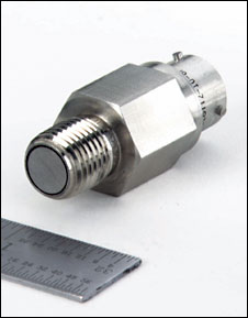
| Figure 3-8: Typical Piezoelectric Pressure Sensor
|
Piezoelectric
When pressure, force or acceleration is applied to a quartz crystal, a charge is developed across the crystal that is proportional to the force applied (Figure 3-8). The fundamental difference between these crystal sensors and static-force devices such as strain gages is that the electric signal generated by the crystal decays rapidly. This characteristic makes these sensors unsuitable for the measurement of static forces or pressures but useful for dynamic measurements. (This phenomenon also is discussed in later chapters devoted to the measurement of dynamic force, impact, and acceleration.)
Piezoelectric devices can further be classified according to whether the crystal's electrostatic charge, its resistivity, or its resonant frequency electrostatic charge is measured. Depending on which phenomenon is used, the crystal sensor can be called electrostatic, piezoresistive, or resonant.
When pressure is applied to a crystal, it is elastically deformed. This deformation results in a flow of electric charge (which lasts for a period of a few seconds). The resulting electric signal can be measured as an indication of the pressure which was applied to the crystal. These sensors cannot detect static pressures, but are used to measure rapidly changing pressures resulting from blasts, explosions, pressure pulsations (in rocket motors, engines, compressors) or other sources of shock or vibration. Some of these rugged sensors can detect pressure events having "rise times" on the order of a millionth of a second, and are described in more detail later in this chapter.
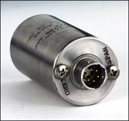 |
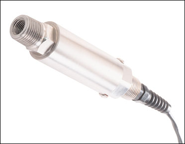
Analog pressure transmitter with
adjustable zero and span.
|
The output of such dynamic pressure sensors is often expressed in "relative" pressure units (such as psir instead of psig), thereby referencing the measurement to the initial condition of the crystal. The maximum range of such sensors is 5,000 or 10,000 psir. The desirable features of piezoelectric sensors include their rugged construction, small size, high speed, and self-generated signal. On the other hand, they are sensitive to temperature variations and require special cabling and amplification.
They also require special care during installation: One such consideration is that their mounting torque should duplicate the torque at which they were calibrated (usually 30 in.-lbs). Another factor that can harm their performance by slowing response speed is the depth of the empty cavity below the cavity. The larger the cavity, the slower the response. Therefore, it is recommended that the depth of the cavity be minimized and not be deeper than the diameter of the probe (usually about 0.25-in.).
Electrostatic pressure transducers are small and rugged. Force to the crystal can be applied longitudinally or in the transverse direction, and in either case will cause a high voltage output proportional to the force applied. The crystal's self-generated voltage signal is useful where providing power to the sensor is impractical or impossible. These sensors also provide high speed responses (30 kHz with peaks to 100 kHz), which makes them ideal for measuring transient phenomena.
 |
Figure 3-9: Acceleration-Compensated
Piezoelectric Sensor
|
Figure 3-9 illustrates an acceleration-compensated pressure sensor. In this design, the compensation is provided by the addition of a seismic mass and a separate "compensation crystal" of reverse polarity. These components are scaled to exactly cancel the inertial effect of the masses (the end piece and diaphragm) which act upon the pressure-sensing crystal stack when accelerated.
Because quartz is a common and naturally occurring mineral, these transducers are generally inexpensive. Tourmaline, a naturally occurring semi-precious form of quartz, has sub-microsecond responsiveness and is useful in the measurement of very rapid transients. By selecting the crystal properly, the designer can ensure both good linearity and reduced temperature sensitivity.
Although piezoelectric transducers are not capable of measuring static pressures, they are widely used to evaluate dynamic pressure phenomena associated with explosions, pulsations, or dynamic pressure conditions in motors, rocket engines, compressors, and other pressurized devices that experience rapid changes. They can detect pressures between 0.1 and 10,000 psig (0.7 KPa to 70 MPa). Typical accuracy is 1% full scale with an additional 1% full scale per 1000¡ temperature effect.
Piezoresistive pressure sensors operate based on the resistivity dependence of silicon under stress. Similar to a strain gage, a piezoresistive sensor consists of a diaphragm onto which four pairs of silicon resistors are bonded. Unlike the construction of a strain gage sensor, here the diaphragm itself is made of silicon and the resistors are diffused into the silicon during the manufacturing process. The diaphragm is completed by bonding the diaphragm to an unprocessed wafer of silicon.
If the sensor is to be used to measure absolute pressure, the bonding process is performed under vacuum. If the sensor is to be referenced, the cavity behind the diaphragm is ported either to the atmosphere or to the reference pressure source. When used in a process sensor, the silicon diaphragm is shielded from direct contact with the process materials by a fluid-filled protective diaphragm made of stainless steel or some other alloy that meets the corrosion requirements of the service.
Piezoresistive pressure sensors are sensitive to changes in temperature and must be temperature compensated. Piezoresistive pressure sensors can be used from about 3 psi to a maximum of about 14,000 psi (21 KPa to 100 MPa).
Resonant piezoelectric pressure sensors measure the variation in resonant frequency of quartz crystals under an applied force. The sensor can consist of a suspended beam that oscillates while isolated from all other forces. The beam is maintained in oscillation at its resonant frequency. Changes in the applied force result in resonant frequency changes. The relationship between the applied pressure P and the oscillation frequency is:
where TO is the period of oscillation when the applied pressure is zero, T is the period of oscillation when the applied pressure is P, and A and B are calibration constants for the transducer.
These transducers can be used for absolute pressure measurements with spans from 0-15 psia to 0-900 psia (0-100 kPa to 0-6 MPa) or for differential pressure measurements with spans from 0-6 psid to 0-40 psid (0-40 kPa to 0-275 kPa).
 |
| Figure 3-10: Magnetic Pressure Transducer Designs
|
Inductive/Reluctive
A number of early pressure transducer designs were based on magnetic phenomena. These included the use of inductance, reluctance, and eddy currents. Inductance is that property of an electric circuit that expresses the amount of electromotive force (emf) induced by a given rate of change of current flow in the circuit. Reluctance is resistance to magnetic flow, the opposition offered by a magnetic substance to magnetic flux. In these sensors, a change in pressure produces a movement, which in turn changes the inductance or reluctance of an electric circuit.
 |
Flush-mount pressure sensor fits
1/4-in. NPT threads.
|
Figure 3-10A illustrates the use of a linear variable differential transformer (LVDT) as the working element of a pressure transmitter. The LVDT operates on the inductance ratio principle. In this design, three coils are wired onto an insulating tube containing an iron core, which is positioned within the tube by the pressure sensor.
Alternating current is applied to the primary coil in the center, and if the core also is centered, equal voltages will be induced in the secondary coils (#1 and #2). Because the coils are wired in series, this condition will result in a zero output. As the process pressure changes and the core moves, the differential in the voltages induced in the secondary coils is proportional to the pressure causing the movement.
LVDT-type pressure transducers are available with 0.5% full scale accuracy and with ranges from 0-30 psig (0-210 kPa) to 0-10,000 psig (0-70 MPa). They can detect absolute, gauge, or differential pressures. Their main limitations are susceptibility to mechanical wear and sensitivity to vibration and magnetic interference.
Reluctance is the equivalent of resistance in a magnetic circuit. If a change in pressure changes the gaps in the magnetic flux paths of the two cores, the ratio of inductances L1/L2 will be related to the change in process pressure (Figure 3-10B). Reluctance-based pressure transducers have a very high output signal (on the order of 40 mV/volt of excitation), but must be excited by ac voltage. They are susceptible to stray magnetic fields and to temperature effects of about 2% per 1000¡ F. Because of their very high output signals, they are often used in applications where high resolution over a relatively small range is desired. They can cover pressure ranges from 1 in. water to 10,000 psig (250 Pa to 70 MPa). Typical accuracy is 0.5% full scale.
 |
| Figure 3-11: Optical Pressure Transducer
|
Optical
Optical pressure transducers detect the effects of minute motions due to changes in process pressure and generate a corresponding electronic output signal (Figure 3-11). A light emitting diode (LED) is used as the light source, and a vane blocks some of the light as it is moved by the diaphragm. As the process pressure moves the vane between the source diode and the measuring diode, the amount of infrared light received changes.
The optical transducer must compensate for aging of the LED light source by means of a reference diode, which is never blocked by the vane. This reference diode also compensates the signal for build-up of dirt or other coating materials on the optical surfaces. The optical pressure transducer is immune to temperature effects, because the source, measurement and reference diodes are affected equally by changes in temperature. Moreover, because the amount of movement required to make the measurement is very small (under 0.5 mm), hysteresis and repeatability errors are nearly zero.
Optical pressure transducers do not require much maintenance. They have excellent stability and are designed for long-duration measurements. They are available with ranges from 5 psig to 60,000 psig (35 kPa to 413 MPa) and with 0.1% full scale accuracy.
Practical Considerations
In industrial applications, good repeatability often is more important then absolute accuracy. If process pressures vary over a wide range, transducers with good linearity and low hysteresis are the preferred choice.
Ambient and process temperature variations also cause errors in pressure measurements, particularly in detecting low pressures and small differential pressures. In such applications, temperature compensators must be used.
 |
Thick-film silicon pressure sensor is available in ranges
from 10 to 30,000 psia.
|
Power supply variations also lower the performance of pressure transducers. The sensitivity (S) of a transducer determines the amount of change that occurs in the output voltage (VO) when the supply voltage (VS) changes, with the measured pressure (Pm) and the rated pressure of the transducer (Pr) remaining constant:

In a pressure measurement system, the total error can be calculated using the root-sum-square method: the total error is equal to the square root of the sums of all the individual errors squared.
Selection Criteria
Pressure transducers usually generate output signals in the millivolt range (spans of 100 mV to 250 mV). When used in transmitters, these are often amplified to the voltage level (1 to 5 V) and converted to current loops, usually 4-20 mA dc.
The transducer housing should be selected to meet both the electrical area classification and the corrosion requirements of the particular installation. Corrosion protection must take into account both splashing of corrosive liquids or exposure to corrosive gases on the outside of the housing, as well as exposure of the sensing element to corrosive process materials. The corrosion requirements of the installation are met by selecting corrosion-resistant materials, coatings, and by the use of chemical seals, which are discussed later in this chapter.
If the installation is in an area where explosive vapors may be present, the transducer or transmitter and its power supply must be suitable for these environments. This is usually achieved either by placing them inside purged or explosion-proof housings, or by using intrinsically safe designs.
Probably the single most important decision in selecting a pressure transducer is the range. One must keep in mind two conflicting considerations: the instrument's accuracy and its protection from overpressure. From an accuracy point of view, the range of a transmitter should be low (normal operating pressure at around the middle of the range), so that error, usually a percentage of full scale, is minimized. On the other hand, one must always consider the consequences of overpressure damage due to operating errors, faulty design (waterhammer), or failure to isolate the instrument during pressure-testing and start-up. Therefore, it is important to specify not only the required range, but also the amount of overpressure protection needed.
 |
| Figure 3-12: Bourdon Tube Overpressure Protection
|
Most pressure instruments are provided with overpressure protection of 50% to 200% of range (Figure 3-12). These protectors satisfy the majority of applications. Where higher overpressures are expected and their nature is temporary (pressure spikes of short duration--seconds or less), snubbers can be installed. These filter out spikes, but cause the measurement to be less responsive. If excessive overpressure is expected to be of longer duration, one can protect the sensor by installing a pressure relief valve. However, this will result in a loss of measurement when the relief valve is open.
If the transmitter is to operate under high ambient temperatures, the housing can be cooled electrically (Peltier effect) or by water, or it can be relocated in an air-conditioned area. When freezing temperatures are expected, resistance heating or steam tracing should be used in combination with thermal insulation.
When high process temperatures are present, one can consider the use of various methods of isolating the pressure instrument from the process. These include loop seals, siphons, chemical seals with capillary tubing for remote mounting, and purging.
|