|
|
 |

Maintenance
Without exception, pressure sensors require scheduled, periodic maintenance and/or recalibration. It is necessary to periodically remove the transducer from the process and to make sure that this procedure does not require shutting down the process and does not cause injury or damage. Because the process fluid may be toxic, corrosive, or otherwise noxious to personnel or the environment, it is necessary to protect against the release of such fluids during maintenance.
 |
Figure 3-13: Three-Valve Manifold for
Instrument Isolation
|
A three-way manifold (Figure 3-13) can provide such protection. In the illustration, valve P is used to isolate the process and valve D serves to discharge the trapped process fluid from the instrument into some safe containment. The purpose of valve T is to allow the application of a known calibration or test pressure to the instrument. As all the components of the manifold are pre-assembled into a compact package, space and field assembly time are saved and chances for leaks are reduced.
Calibration
Pressure transducers can be recalibrated on-line or in a calibration laboratory. Laboratory recalibration typically is preferred, but often is not possible or necessary. In the laboratory, there usually are two types of calibration devices: deadweight testers that provide primary, base-line standards, and "laboratory" or "field" standard calibration devices that are periodically recalibrated against the primary. Of course, these secondary standards are less accurate than the primary, but they provide a more convenient means of testing other instruments.
A deadweight tester consists of a pumping piston with a screw that presses it into the reservoir, a primary piston that carries the dead weight, and the gauge or transducer to be tested (Figure 3-14). It works by loading the primary piston (of cross sectional area A), with the amount of weight (W) that corresponds to the desired calibration pressure (P = W/A). The pumping piston then pressurizes the whole system by pressing more fluid into the reservoir cylinder, until the dead weight lifts off its support.
 |
| Figure 3-14: Dead-Weight Tester Schematic
|
Today's deadweight testers are more accurate and more complex than the instrument in Figure 3-14, but the essential operating principles are the same. Sophisticated features include temperature compensation and the means to rotate the piston in its cylinder to negate the effects of friction.
In the United States, the National Institute of Standards & Technology (NIST) provides certified weights and calibrates laboratory piston gauges by measuring the diameter of the piston. Deadweight testers can be used to calibrate at pressure levels as low as 5 psig (35 kPa) and as high as 100,000 psig (690 MPa). Tilting type, air-lubricated designs can detect pressures in the mm Hg range. NIST calibrated deadweight testers can be accurate to 5 parts in 100,000 at pressures below 40,000 psig (280 MPa). For an industrial quality deadweight tester, error is typically 0.1% of span.
A typical secondary standard used for calibrating industrial pressure transducers contains a precision power supply, an accurate digital readout, and a high-accuracy resonant (quartz) pressure sensor. It is precise enough to be used to calibrate most industrial pressure transducers, but must be NIST-traceable to be used as an official calibration standard. The best accuracy claimed by the manufacturers is typically 0.05% full scale.
Installation & Accessories
When possible, pressure instrumentation should be installed in visible, readily accessible locations. Readouts should be located at eye elevation. Headroom should be provided for instrument removal, as well as any space for tools and test equipment that might be needed.
In some applications, it is desirable to prevent the process fluid from coming in contact with the sensing element. The process may be noxious, poisonous, corrosive, abrasive, have the tendency to gel, freeze or decompose at ambient temperatures, or be hotter or colder than the sensor can tolerate. Other reasons for inserting accessories between the process and the pressure instrument are to filter out potentially plugging solids or to remove potentially damaging pressure spikes or vibrations.
 |
| Figure 3-15: Pulsation Damper & Snubber Designs
|
Snubbers & Pulsation Dampers
An unprotected pressure sensor on the discharge of a positive displacement pump or compressor would never come to rest, and its pointer would cycle continuously. To filter out pressure spikes, or to average out pressure pulses, snubbers and pulsation dampers are installed between the process and the instrument (Figure 3-15).
The first design shown in the illustration uses a corrosion-resistant porous metal filter to delay the pressure reading by about 10 seconds. Other designs provide shorter delays via fixed or variable pistons or restrictions. The advantage of an adjustable restriction is that if, for example, a pressure gauge is placed on the discharge of a compressor, one can see when the pointer cycling has stopped. Naturally, when one is interested in the measurement of fast, transient pressures (such as to initiate safety interlocks on rising pressures), snubbers must not be used, as they delay the response of the safety system.
 |
| Figure 3-16: Chemical Seal Alternatives |
Chemical Seals
The chemical seal is also known as a "diaphragm protector." Its main components (the upper and lower body and the clean-out ring) are shown in Figure 3-16A. The pressure instrument is screwed into the upper body, which can be made of standard materials because it contacts only the non-corrosive filling fluid, usually a silicone oil. The top section with the filled diaphragm capsule can be removed with the pressure instrument while the operator cleans out the material accumulated in the bottom housing. This lower body is made of "pipe specification" (process compatible) materials and can be continuously or periodically cleaned by purging.
The seal shown in Figure 3-16A is an off-line design; an in-line design is shown in Figure 3-16B. In-line devices are less likely to plug, but the process has to be shut down if maintenance is required. The ultimate in self-cleaning designs is shown in Figure 3-16C, in which all sharp edges and dead-ended cavities (where solids could accumulate) have been eliminated. The flexible cylinder can be made of a variety of plastics, including PFA, and is available in spool and wafer configurations.
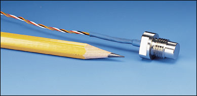 |
| Miniature pressure sensor fits in tight spots.
|
As the process pressure changes, the amount of liquid displaced by the sealing diaphragm is small, and is sometimes insufficient to fill and operate bellows-type sensors. In that case, larger displacement "rolling" diaphragms are used. Volumetric seal elements (Figure 3-17) also can eliminate cavities and sharp edges where material might accumulate. They also are well suited for high pressure and high viscosity applications such as extruders.
 |
| Figure 3-17: Volumetric Seal Element Designs |
Adding seals to a press measurement device can cause the following problems:
Long or large bore capillaries increase the volume of the filling fluid, increasing the temperature error.
Smaller diameter diaphragms are stiff and increase error, particularly at low temperatures.
Filling fluid viscosity, acceptable at normal ambient temperatures, may be unacceptably high at low temperatures.
Long capillary lengths or smaller bores can cause slow response.
Uneven heating/cooling of seals and capillaries can cause errors.
Some fill fluids expand excessively with temperature and damage the instrument by overextending the diaphragm.
High temperature and/or high vacuum may vaporize the fill fluid and damage the instrument.
Fluid may contract excessively at low temperatures, bottoming the diaphragm and preventing operation.
Frozen fill fluid also will prevent operation.
For a successful seal installation, the following must also be considered:
Process and ambient temperature range.
Relative elevation of the seals and the instrument and the hydrostatic head of the fill fluid. Instrument should be rezeroed after installation to correct for elevation.
Temperature, pressure, and physical damage potentials during cleaning and emptying.
Possible consequences of diaphragm rupture in terms of hazard and contamination.
Identical seals and capillary lengths for both sides of a differential pressure device.
Seal and instrument performance at maximum temperature/minimum pressure and minimum pressure/temperature combinations.
Wet Legs & Seal Pots
When one or both impulse lines to a differential pressure device are filled with a stable, process compatible fluid, the installation is called a "wet-leg" installation. The net effect of the legs' height above the instrument and specific gravity of the fluid must be considered in the calibration. Wet leg design must also allow for the filling and draining of the leg(s).
Seal pots are used with wet legs when the instrument displaces a large volume of liquid as the measurement changes. A seal pot is a small pressure vessel about one quart in volume that is mounted at the top of the wet leg line. If two wet legs are used in a differential application, the pots must be mounted at the same elevation. Each pot acts as a reservoir in the impulse line where large volume changes will result in minimal elevation change so that seal liquid is not dumped into the process line and elevation shifts of the wet leg liquid do not cause measurement errors.
| |
References & Further Reading |
| |
Omegadyne Pressure, Force, Load, Torque Databook, Omegadyne, Inc., 1996. |
| |
The Pressure, Strain, and Force Handbook, Omega Press LLC, 1996. |
| |
Industrial Control Handbook, E. A. Parr, Butterworth, 1995. |
| |
Instrument Engineers' Handbook, Bela Liptak, CRC Press LLC, 1995. |
| |
Marks' Standard Handbook for Mechanical Engineers, 10th Edition, Eugene A. Avallone, and Theodore Baumeister, McGraw-Hill, 1996. |
| |
"Pressure Transducers," Raymond Williams, Flow Control, March, 1998. |
| |
Process/Industrial Instruments and Controls Handbook, 4th Edition, Douglas M. Considine, McGraw-Hill, 1993. |
| |
Van Nostrand's Scientific Encyclopedia, Douglas M. Considine and Glenn D. Considine, Van Nostrand, 1997. |
|