|
|
 |

D/A Conversion
Analog outputs commonly are used to operate valves and motors in industrial environments and to generate inputs for electronic devices under test. Digital-to-analog (D/A) conversion is in many ways the converse of A/D conversion, but tends to be generally more straightforward. Similar to analog input configurations, a common D/A converter often is shared among multiplexed output signals. Standard analog output ranges are essentially the same as analog inputs: ±5 V dc, ±10 V dc, 0-10 V dc, and 4-20 mA dc.
Essentially, the logic circuitry for an analog voltage output uses a digital word, or series of bits, to drop in (or drop out, depending on whether the bit is 1 or 0) a series of resistors from a circuit driven by a reference voltage. This ladder of resistors can be made of either weighted value resistors or an R-2R network using only two resistor values-one if placed in series (Figure 1-13).
While operation of the weighted-value network is more intuitively obvious, the R-2R scheme is more practical. Because only one resistor value need be used, it is easier to match the temperature coefficients of an R-2R ladder than a weighted network, resulting in more accurate outputs. Plus, for high resolution outputs, very high resistor values are needed in the weighted-resistor approach.
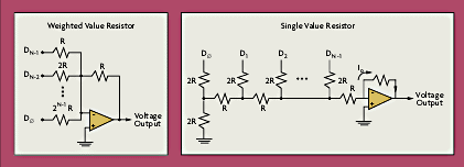 |
| Figure 1-13: Weighted Value & Single Value Resistor Networks for D/A Conversion |
Key specifications of an analog output include:
Settling time: Period required for a D/A converter to respond to a full-scale setpoint change.
Linearity: This refers to the device's ability to accurately divide the reference voltage into evenly sized increments.
Range: The reference voltage sets the limit on the output voltage achievable.
Because most unconditioned analog outputs are limited to 5 mA of current, amplifiers and signal conditioners often are needed to drive a final control element. A low-pass filter may also be used to smooth out the discrete steps in output.
| |
References and Further Reading |
| |
The Data Acquisition Systems Handbook, Omega Press LLC, 1997. |
| |
New Horizons in Data Acquisition and Computer Interfaces, Omega Press LLC, 1997. |
| |
Omega® Universal Guide to Data Acquisition and Computer Interfaces, Omega Press LLC, 1997. |
| |
Analog I/O Design: Acquisition, Conversion, Recovery, Patrick Garrett, Reston Publishing Co., 1981. |
| |
Analog Signal Processing and Instrumentation, Arie F. Arbel, Cambridge University Press, 1980. |
| |
Analog-To-Digital and Digital-To-Analog Conversion Techniques, David Hoeschele, John Wiley & Sons, 1994. |
| |
Analog-To-Digital Conversion: A Practical Approach, Kevin M. Daughtery, McGraw Hill, 1995. |
| |
Automation Systems for Control and Data Acquisition, Lawrence T. Amy, ISA, 1992. |
| |
Data Acquisition and Control, Microcomputer Applications for Scientists and Engineers, Joseph J. Carr, Tab Books Inc., 1988. |
| |
Data Acquisition and Process Control Using Personal Computers, Tarik Ozkul, Marcel Dekker, 1996. |
| |
Instrument Engineers' Handbook, Third Edition, Bela Liptak, Chilton Book Co., 1995. |
| |
Process/Industrial Instruments & Controls Handbook, Fourth Edition, Douglas M. Considine, McGraw-Hill Inc., 1993. |
| | |
| |
|
|
| Top of Page |
|
Next Chapter: Digital I/O Functionality
|
|