|
|
 |

Plug-in Cards
Data acquisition cards that plug into the chassis of a desktop PC, a PC-compatible industrial computer, or an Apple Macintosh computer have made measurement and control extremely economical for the typical lab or industrial user.
A plug-in data acquisition card with 16 analog input channels in the USD$1,000 to USD$2,000 price range represents a cost of USD$62.50 to USD$125.00 per measurement point. This compares to USD$350 per point (or more) for a conventional "front-end" or communications-based system.
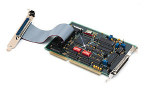 |
This 12-bit data acquisition system provides eight analog inputs,
two analog outputs, and 24 digital I/O-all on a single low-cost PC card. |
In the past, high-speed data acquisition systems required expensive, high-end computer platforms such as VAX/VMS minicomputers or Unix RISC workstations to handle large amounts of real-time data and have enough computing power left over to perform control and operator interface functions. Such systems were expensive to buy, install, maintain, and update.
Today, a PC has the same amount of computing power as yesterday's RISC workstations. Desktop and panel-mounted industrial PCs are available with up to 300-MHz Pentium II processors, enormous amounts of memory, fast disk drives, high-speed networking capability, and powerful operating systems. Mac-based systems have similar capabilities.
Previously, hardware and software for high-end systems were not interchangeable among products from different vendors. Plug-in data acquisition boards for a RISC workstation were scarce and very expensive. Conversely, plug-in data acquisition boards for PCs, compatibles, and Macs are plentiful, relatively inexpensive, and compatible with each other.
Once, setting up a PC-based data acquisition system was very difficult. Hardware and software were primitive, so installation and configuration required setting jumpers and DIP switches, allocating operating system resources, changing config.sys settings, changing IRQ levels, writing software drivers, and performing hardware calibration.
The trend today is toward plug-and-play systems that configure, install, and calibrate themselves. Plug-and-play software selects and assigns system resources automatically.
Many modern data acquisition boards do not require periodic calibration. Those that do often come with autocalibration functions built in.
Plug-in boards offer a great deal of software compatibility, virtually eliminating the need to write drivers or special software to interface them to a system. If you already have software, check to be sure that the data acquisition hardware you are considering is compatible with your system. You can also check with your software supplier to see what data acquisition boards it supports.
A typical plug-in data acquisition board offers these features:
Analog inputs: 8 DE or 16 SE;
Resolution: 12- or 16-bit;
Input range: mV and V;
Sampling rate: 30,000-330,000 samples/second;
Analog outputs: 2;
Digital I/O: 8-16; and
Base price: USD$199 to USD$1,200.
There are hundreds of data acquisition board configurations available for PCs and Macs. Many other boards are available with more inputs, higher resolution, and faster scanning speeds. Now, let's look at some of the higher performance boards.
High-Speed Data Acquisition
A typical plug-in data acquisition card has a sampling rate of 30,000 to 250,000 samples/second. A high-speed data acquisition card, on the other hand, operates at 330,000 to 20 million samples/second. Applications for such high sampling speeds include wind tunnel testing, auto crash testing, video processing, ultrasonic imaging, and waveform analysis.
At such speeds, the data acquisition card must be able to communicate with its computer via direct memory access (DMA). This allows the card to transfer large quantities of data directly to the computer's memory. In some cases, the card may have dual-channel DMA.
A high-speed data acquisition board often has a considerable amount of first-in-first-out (FIFO) memory. Typically, a high-speed data acquisition board can store 64,000 samples. Some can store more than a million samples, either on the board or by using additional memory on daughter boards.
In most cases, the board does not attempt to acquire 20 million samples every second, because it would soon overflow on-board memory, host computer memory, and disk space. Instead, the board waits for an external trigger signal that says an "event" is occurring, and then it begins to acquire data at high sampling rates. Trigger sources can be analog or digital inputs.
A "typical" high speed data acquisition board-above 330,000 samples/second-has these features:
Analog inputs: 8 DE or 16 SE;
Resolution: 12-bit;
Input range: mV and V;
Sampling rate: 330,000 to 1,000,000 samples/second;
Analog outputs: 2;
Digital I/O: 8; and
Base price: USD$595 to USD$2,399.
Often, as speed increases resolution drops to 12-bit. Of course, 14-bit and higher resolutions are available in high speed data acquisition boards at a cost.
One ultra high-speed data acquisition board for radar, ultrasonic, seismic, and related applications acquires data at sample rates up to 500 million samples/sec. Using interleave techniques, rates of up to 1 billion samples/second may be achieved. Boards are available for PC and VME-based systems.
For applications that require-high speed data acquisition, plug-in boards that operate at 330,000 to 1,000,000 samples per second are readily available at reasonable prices. The only sacrifice may be in accuracy and resolution.
 |
Designed to use external signal conditioning cards and a
notebook computer, this unique data acquisition system provides
a good mix of portability, flexibility, and economy. |
High-Accuracy Data Acquisition
For most applications, plug-in data acquisition boards with standard 12- or 16-bit resolution are adequate. Some applications, however, require greater accuracy and resolution. Higher resolution means an A/D converter with more bits. Each bit-size increase means that the computer can resolve twice as much data: for example, a 16-bit data acquisition board can resolve to 1 part in 65,536; increasing to 18 bits quadruples this to 1 part in 262,144.
Data acquisition boards are available with resolutions of 18 bits, 20 bits, and higher. At the higher resolution, much smaller voltage changes can be identified. With a voltage signal of 0-1,000 V, the smallest change the system can see with a 20-bit A/D converter is ±0.0038 V (compared to ±0.015 at 16 bits).
Accuracy also is affected by many other variables. Some of the specifications to consider are:
Code width: This is the smallest voltage an A/D converter can detect. It is a function of resolution, range and gain:
code width = range/(gain x resolution)
For example, a 12-bit data acquisition board with a range of 20 V and a gain of 100 can detect a 48.8 microvolt mV change in signal (0.0000488 = 20/(100 x 4,096)). A 16-bit data acquisition board detects a 0.030 mV change, and so on. It is a common misconception that accuracy is the same as code width.
Settling time: This is the time required by the programmable gain amplifier (PGA) to respond to the input signal. Most data acquisition boards use a multiplexer to switch signals to the PGA. If data is sampled faster than the PGA can respond, errors will occur. For maximum accuracy, select a data acquisition board with a PGA that can respond to the sampling rate needed.
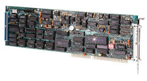 |
High-speed data acquisition boards can exceed one
million
samples per second for applications such as
transient recording and vibration analysis. |
A/D conversion time: This is the time required by the A/D converter for each sample. A high precision A/D converter might require 2.5 ms, making the maximum sampling rate a fairly slow 400 Hz.
Computing accuracy: It is possible to calculate the theoretical accuracy of any data acquisition board, but the computation is relatively complex, taking into account a dozen board performance parameters. I&CS magazine offers the procedure as an Excel worksheet, which can be found on the Internet at: www.chiltonco/ics/calcexam.xls. The file can be downloaded directly into your computer.
Perhaps the most important consideration is that high speed and high accuracy are often mutually exclusive. To obtain maximum accuracy, speed must be sacrificed. This is because:
Accurate A/D converters operate more slowly than low-precision devices.
Data acquisition components must have adequate time to settle and convert to obtain the accuracy they are capable of providing.
Sampling interval may need to be increased to eliminate software skew.
A 20-bit digital value requires 3 bytes of information, 50% more than a 12- or 16-bit value, so it takes 50% more time just to move this data from point to point in the system.
Specialty Data Acquisition Boards
A wide variety of specialty data acquisition boards also are available. In some cases, these are standard data acquisition boards that have been modified to fit a specific application by adding one or more functions, such as high input isolation, timer interface, or specialty software.
Thermocouple and RTD input: These boards permit direct connection of field wiring from temperature sensors without additional external signal conditioning. All necessary linearization, signal conditioning, and noise filtering are done on the data acquisition board itself. Multi-purpose temperature boards usually also accept inputs from strain gages or similar low-level mV signals. Boards also are available to accept thermocouples only (or RTDs only). These boards accept all common thermocouple types, plus mV and voltage signals. A typical board will linearize the thermocouple signal and compute the cold junction compensation. Options include automatic calibration, averaging, and voltage-to-frequency (V/F) sampling to reduce noise.
Sensor direct-connect: Similar to the thermocouple and RTD cards, direct-connect cards allow field-wired sensors to connect directly to the data acquisition board. Sometimes called universal sensor input boards, they accept raw, unconditioned signals from thermocouples, RTDs, thermistors, strain gages, and linear variable displacement transducers (LVDTs), as well as resistance, variable reluctance, frequency, and weight sensors. When using such a board, take care to minimize the length of sensor field wires, because the low-power signals are susceptible to electrical noise.
Load cell interface: This type of data acquisition board performs a dual function. First, it inputs field wiring signals from load cells and strain gages All signal conditioning, filtering, and data conversions are done on the board. Second, it supplies the excitation voltage needed by 6-wire, 350-ohm load cells and strain gages. With optional software, the board can make a PC into a high-speed check weigher, load scale, or truck scale.
Sample-and-hold (S/H): Available as an option on some data acquisition boards or as an accessory, the sample-and-hold function allows a number of channels to be sampled virtually simultaneously, while still allowing the A/D converter to be shared among multiple channels. The S/H function "holds" the data until its buffer is emptied and the data is sent to computer memory. In some cases, the simultaneous S/H function is activated by a trigger. When added as an external accessory, the S/H board essentially acts as a front-end to a plug-in data acquisition board, and minimizes skew problems.
Bus Architecture Options
Plug-in data acquisition cards are designed primarily for two lines of computers: PCs and compatibles, and the Apple Macintosh. Among these, several types of bus architectures are available. Selecting the proper bus architecture is important-the wrong choice can limit or thwart expansion plans.
Following is a description of the various buses available (Figure 5-1):
| Figure 5-1: Computer Bus Architectures |
BUS
ACRONYM |
BUS DEFINITION |
NUMBER OF BITS |
MAXIMUM SPEED
(millions of bits/
second, Mbps) |
| ISA |
Industry Standard Architecture |
8, 16 |
1.6 |
| EISA |
Extended ISA |
8, 16, 32 |
33 |
| MCA |
Micro Channel Architecture |
16, 32 |
33 |
| VESA |
Video Electronics Standards Association |
32 |
132 |
| PCMCIA |
Personal Computer Memory Card
International Association |
8, 16, 32 |
132 |
| PCI |
Peripheral Component Interconnect |
32, 64 |
132, 1056 |
| PC/104 |
(ISA in a smaller, more rugged form factor) |
32 |
132 |
| USB |
Universal Serial Bus |
|
12 |
| NuBus |
(Macintosh bus) |
32 |
33 |
| PDS |
Processor Direct Slot (Macintosh bus) |
32 |
132 |
ISA: The first Industry Standard Architecture (ISA) bus was introduced with the original 8088-based PC/XT in 1980. It can address 8- and 16-bit devices, and has DMA capability. When the 16-bit 80386 PC/AT was introduced, it kept the original 8-bit bus, but added a 16-bit connector for 16 data lines and 24 address lines. This did not increase bus speed, but it allowed the bus to address more memory. Neither of the ISA buses can act as a bus master. Many plug-in boards list both PC/XT and PC/AT compatibility, and many modern computers still have one or more ISA expansion slots.
EISA (Extended ISA): Another progression of ISA, this generation added support for intelligent bus-master expansion cards. This is important because if the data acquisition board cannot take control as a bus master, it may not be able to transfer data any faster than an ordinary ISA board. With bus mastering, the data acquisition board makes the DMA transfer at the highest possible rate. EISA supports 8-, 16-, and 32-bit data transfers at speeds up to 33 Mbps.
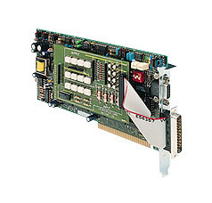 |
This specialized data acquisition board is designed
to handle strain gage inputs for load-cell applications. |
MCA: The ill-fated Micro Channel Architecture is a feature of IBM's PS/2 computer. Its proprietary architecture thwarted PC-compatible manufacturers, so it was never a success outside IBM. Few plug-in data acquisition boards are available for the MCA system.
VESA: The Video Electronics Standards Association developed the VESA bus primarily to maximize throughput for video graphics in the 80386/486 environment. It adds a local bus for faster access to the processor, and supports limited data bursts up to 132 Mbps. Like the MCA bus, it enjoys only limited success outside its industry, and few plug-in data acquisition boards are available for it. Those that are available typically are intended for use in the video industry.
PCMCIA: The Personal Comp-uter Memory Card International Association (PCMCIA) developed this interface for small computers, such as notebooks and laptops. Its popularity skyrocketed, and today virtually every portable PC has PCMCIA slots. It supports 8-, 16-, and 32-bit data transfers. Plug-in data acquisition boards are available that operate at speeds to 100 kHz.
PCI: The Peripheral Component Interconnect (PCI) bus is a processor-independent bus that supports up to 64-bit addressing, bus mastering, and burst transfer rates up to 1,056 Mbps (132 Mbytes/second). The standard is still evolving, with developments such as the CompactPCI standard for industrial applications, and hybrid versions that work with VME, PMC, Multibus, and STD. Virtually every Pentium PC being shipped today has a combination of ISA/PCI or EISA/PCI buses.
PC/104: Intended for embedded computer applications, PC/104 cards are very compact at 3.6 x 3.8 in. PC/104 also allows card modules to self-stack without backplanes or card cages, and has pin-and-socket bus connectors designed for high reliability in harsh environments. It is, essentially, a miniaturized version of the standard PC bus architecture. Also in continual development, the latest generation (PC/104-Plus) operates at the same speed as PCI.
USB: The Universal Serial Bus (USB) is around the corner. Currently being offered in most commercial PCs, it is essentially an upgrade of the venerable RS-232 port. It will allow up to 127 USB devices to connect to a PC. USB peripherals will be automatically detected and configured when connected and could include virtually every peripheral device now being used, including keyboards, monitors, touchscreens, modems, and data acquisition devices. It operates at 12 Mbps. Almost no industrial data acquisition boards are available today, but many companies have them in development.
Buses for Apple computers are not nearly as complicated and diverse as PC buses, but specs vary from model to model. Until recently, Apple buses were based on two basic architectures: NuBus and Processor Direct Slot (PDS). Both are 32 bits wide. The NuBus is found in almost every Macintosh computer, while PDS provides very high-speed communications.
It is more interesting to look at the latest Macintosh to see what direction Apple is going. Its latest computer, the Power Macintosh G3 has a 233 or 266 MHz PowerPC processor and two processor buses: a standard 66 MHz system bus and a 133 MHz "backside" bus for 64-bit data transfers.
The G3 also comes with three 12-in. PCI expansion slots that are compatible with PCI 2.1 cards, two high speed DMA serial ports, and a built-in 10BaseT Ethernet connector, presumably for Internet/intranet connections.
Anyone considering plug-in data acquisition boards for either PC or Mac systems can be confident that both the computer processing hardware and the data acquisition boards are capable of handling just about any data acquisition job imaginable.
|