Vortex Flow Meter
What is a Vortex Flow Meter?
A vortex flow meter is a flow measurement device best suited for flow measurements where the introduction of moving parts presents problems. They are available
in industrial grade, brass or all plastic construction. Sensitivity to variations in the process conditions are low and with no moving parts have relatively
low wear compared to other types of flow meters.
Vortex flow meters operate under the vortex shedding principle, where an oscillating vortexes occur when a fluid such as water flow past a bluff (as opposed
to streamlined) body. The frequency that the vortexes are shed depend on the size and shape of the body. It is ideal for applications where low maintenance
costs are important. Industrial size vortex meters are custom built and require appropriate sizing for specific applications.
What is a Vortex Flow Meter?
Common Vortex Shedding Phenomenon
The vortex-shedding phenomenon can be observed as wind is shed from a flagpole: it is
what causes the regular rippling in a flag. Vortices are also shed from bridge piers, pilings,
offshore drilling platform supports, and tall buildings. The forces caused by the vortex-shedding phenomenon must be
taken into account when designing these structures.
Vortex-Shedding History
Theodore von Karman, a Hungarian-American physicist, was the first to describe the effect where a non-streamlined object (also called a bluff body) placed in the
path of a fast-flowing stream, causes the fluid to alternately separate from the object on its two downstream sides, and, as the boundary layer becomes detached and curls back on itself,
forming vortices (also called whirlpools or eddies). He also noted that the distance between the vortices was constant and depended solely
on the size of the rock that formed it.
On the side of the bluff body where the vortex is being formed, the fluid velocity is higher and the pressure is lower. As the vortex moves
downstream, it grows in strength and size, and eventually detaches or sheds itself. This is followed by a vortex's being formed on the other
side of the bluff body. The alternating vortices are spaced at equal distances.
Vortex Meter Design
A vortex flowmeter is typically made of 316 stainless steel or Hastelloy® and includes a bluff body, a vortex sensor assembly and the transmitter
electronics, although the latter can also be mounted remotely. They are typically available in flange sizes from 1/2 in. to 12 in.
The installed cost of vortex meters is competitive with that of orifice meters in sizes under six inches. Wafer body meters (flangeless) have the
lowest cost, while flanged meters are preferred if the process fluid is hazardous or is at a high temperature.
Bluff body shapes (square, rectangular, t-shaped, trapezoidal) and dimensions have been experimented with to achieve the desired characteristics.
Testing has shown that linearity, low Reynolds number limitation, and sensitivity to velocity profile distortion vary only slightly with bluff
body shape. In size, the bluff body must have a width that is a large enough fraction of the pipe diameter that the entire flow participates in
the shedding. Second, the bluff body must have protruding edges on the upstream face to fix the lines of flow separation, regardless of the flow rate.
Third, the bluff body length in the direction of the flow must be a certain multiple of the bluff body width.
The majority of vortex meters uses piezoelectric or capacitance-type sensors to detect the pressure oscillation around the bluff body. These
detectors respond to the pressure oscillation with a low voltage output signal which has the same frequency as the oscillation. Such sensors are
modular, inexpensive, easily replaced, and can operate over a wide range of temperature ranges--from cryogenic liquids to superheated steam. Sensors
can be located inside the meter body or outside. Wetted sensors are stressed directly by the vortex pressure fluctuations and are enclosed in hardened
cases to withstand corrosion and erosion effects.
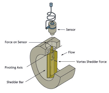
External sensors, typically piezoelectric strain gages, sense the vortex shedding indirectly through the force exerted on the shedder bar. External
sensors are preferred on highly erosive/corrosive applications to reduce maintenance costs, while internal sensors provide better rangeability
(better low flow sensitivity). They are also less sensitive to pipe vibrations. The electronics housing usually is rated explosion- and weatherproof,
and contains the electronic transmitter module, termination connections, and optionally a flow-rate indicator and/or totalizer.
Key Elements to Consider before Choosing a Vortex Flow Meter
1. What is the fluid being measured?
2. Pressure Maxium and Minimum
3. Flowrate Ranges
4. Fluid Temperature
5. Fluid Density Range
6. Viscosity Range
7. Pipe Size
8. Maximum Acceptable Pressure Drop
9. Pipe Schedule or Wall Thickness
10. Pipe Material
11. Nearest Upstream Obstruction
Vortex Flow Meter Styles
Smart vortex meters provide a digital output signal containing more information than just flow rate. The microprocessor in the flowmeter can automatically
correct for insufficient straight pipe conditions, for differences between the bore diameter and that of the mating pipe, for thermal expansion of the bluff
body, and for K-factor changes when the Reynolds number drops below 10,000.
Intelligent transmitters are also provided with diagnostic subroutines to signal component or other failures. Smart transmitters can initiate testing routines
to identify problems with both the meter and with the application. These on-demand tests can also assist in ISO 9000 verification.
Some vortex flowmeters can detect mass flow. One such design measures both the vortex frequency and the vortex pulse strength simultaneously.
From these readings, the density of the process fluid can be determined and the mass flow calculated to within 2% of span.
Another design is provided with multiple sensors to detect not only the vortex frequency, but also the temperature and pressure of the process fluid.
Based on that data, it determines both the density and the mass flow rate. This meter offers a 1.25% of rate accuracy when measuring the mass flow of liquids
and a 2% of rate accuracy for gases and steam. If knowledge of process pressure and temperature is of value for other reasons, this meter provides a convenient,
less costly alternative to installing separate transmitters.
Vortex Flow Meter Styles
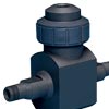 Vortex Flow Meter for Corrosive Liquids
With no moving parts, all electronics are housed in a corrosion-resistant enclosure. Unlike meters containing metal or moving parts,
the plastic vortex meters are perfect for aggressive or easily contaminated fluids. Applications range from ultra-pure water
to highly corrosive chemicals and slurries.
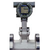 Industrial Vortex Flow Meters
Measures Steam, Gas, and Low Viscosity Liquids. Vortices generated by the flowing fluid stress the shedder
bar in pulses, and the shedder bar transmits the stress pulses to the encapsulated piezoelectric sensor.
 Wedge Flow Meters
Provides a simple and reliable restriction for sensing flow as related to pressure differential. It allows users to install the meter
in any full pipe orientation (horizontal, vertical or inverted). It is usually compact and rugged, offering several
ranges of calibration to accommodate the requirements typical to process water applications.
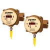 Vortex Shedding Flow Meter
Operating under the same principle of the vortex shedding measurement, this type of vortex flow meter is suitable for viscous,clean, or dirty waterlike
liquids that are compatible with brass, PVDF, and FKM. These applications are found in most process industries, including rubber, steel, fabrication,
manufacturing, refining, paper, chemical, food, petrochemical and power. Are not for suitable for flammable liquids or on gases such as air.
Frequently Asked Questions
Applications & Limitations
Vortex meters are not usually recommended for batching or other intermittent flow applications. This is because the dribble flow-rate setting of the batching station
can fall below the meter's minimum Reynolds number limit. The smaller the total batch, the more significant the resulting error is likely to be.
Low pressure (low density) gases do not produce a strong enough pressure pulse, especially if fluid velocities are low. Therefore, it is likely that in such services
the rangeability of the meter will be poor and low flows will not be measurable. On the other hand, if reduced rangeability is acceptable and the meter is correctly
sized for normal flow, the vortex flowmeter can still be considered.
If the process fluid tends to coat or build-up on the bluff body, as in sludge and slurry service, this will eventually change the meter's K factor. Vortex-shedding
flowmeters are not recommended for such applications. If, however, a dirty fluid has only moderate amounts of non-coating solids, the application is likely to be
acceptable. This was demonstrated by a 2-year test on a limestone slurry. At the end of the test, the K factor was found to have changed only 0.3% from the original
factory calibration, although the bluff body and flowtube were badly scarred and pitted.
When measuring multi-phase flow (solid particles in gas or liquid; gas bubbles in liquid; liquid droplets in gas), vortex meter accuracy will drop because of the
meter's inability to differentiate between the phases. Wet, low-quality steam is one such application: the liquid phase should be homogeneously dispersed within the
steam, and vertical flow lines should be avoided to prevent slugging. When the pipe is horizontal, the liquid phase is likely to travel on the bottom of the pipe,
and therefore the inner area of the pipe should be kept open at the bottom. This can be achieved by installing the bluff body horizontally. Measurement inaccuracy
in such applications is about 5% of actual flow, but with good repeatability.
The permanent pressure loss through a vortex meter is about half that of an orifice plate, roughly two velocity heads. (A velocity head is defined as V2/g, where
V is the flow velocity and g is the gravitational constant in consistent units.) If the pipe and meter are properly sized and of the same size, the pressure drop
is likely to be only a few psi. However, downsizing (installing a smaller-than-line-size meter) in order to increase the Reynolds can increase the head loss to more
than 10 psi. One should also make sure that the vena contracta pressure does not drop below the vapor pressure of the process fluid, because that would cause cavitation.
Naturally, if the back-pressure on the meter is below the vapor pressure, the process fluid will flash and the meter reading will not be meaningful.
The main advantages of vortex meters are their low sensitivity to variations in process conditions and low wear relative to orifices or turbine meters. Also,
initial and maintenance costs are low. For these reasons, they have been gaining wider acceptance among users.
Installation Recommendations
When installing a vortex flowmeter in an existing process where the flow range is not known, it is recommended to first make some approximate measurements
(using portable pitot or clamp-on ultrasonic devices). Otherwise, there is no guarantee that a line-size vortex meter will work at all.
The vortex meter requires a well-developed and symmetrical flow velocity profile, free from any distortions or swirls. This necessitates the use of straight up-
and downstream piping to condition the flow. The straight length of pipe must be the same size as the meter and its length should be about the same
as required for an orifice installation with a beta ratio of 0.7. Most vortex flowmeter manufacturers recommend a minimum of 30 pipe diameters
downstream of control valves, and 3 to 4 pipe diameters between the meter and downstream pressure taps. Temperature elements should be small and located 5 to
6 diameters downstream.
About half of all vortex meter installations require the "necking down" of oversized process piping by concentric reducers and expanders. Even if flow straighteners
are installed, some straight (relaxation) piping will still be required.
Vortex meters can be installed vertically, horizontally, or at any angle, as long as they are kept flooded. The meter can be kept flooded by installing it in a
vertical upward flow line. When installing the flowmeter in a downward or horizontal flow, the downstream piping should
be kept elevated. Check valves can be used to keep the piping full of liquid when there is no flow. Block and bypass valves are required if the replacement of the
sensor in the particular design requires the stopping of the flow and the opening up of the process.
Mating flanges (on the schedule 40 or schedule 80 mating piping) must have the same diameter and smooth bore as the flowmeter. Weld neck flanges are preferred,
and reducing flanges should not be used. The inner surface of the mating pipe should be free from mill scale, pits, holes, reaming scores and bumps for a distance
of 4 diameters upstream and 2 diameters downstream of the meter. The bores of the meter, the gaskets and the adjacent piping must be carefully aligned to eliminate
any obstructions or steps.
Excessive pipe vibration can be eliminated by supporting the piping on both sides of the meter, or by rotating the meter so that the sensor is moved out of the
plane of the vibration. Process noise due to valve chattering, steam traps, or pumps can result in high readings or non-zero readings under zero-flow conditions.
Most meter electronics allow for increasing the noise filter settings, but increased noise reduction usually also decreases the low-flow sensitivity of the meter.
One option is to relocate the meter to a less noisy part of the process.
 CLOSE
CLOSE